We have uav airborne footage! now to go build a stabilised camera platform with PIDs etc...
here it is!
Also, I am moving the project in a different direction, I going to put less emphasis on fixed wing aircraft and move to a tricopter.There are quite a few people working on this, and there is a lot of common knowledge and hopefully I will contribute too. The build is in progress.I am working on the control boards while saving up for the motors etc..
The final idea that is stirring in my mind is a tricopter with wings. So VSTOL + winged flight to increase flight efficiency.At the moment all will still be arduino based,but if the system demands more, I'm ready to graduate to a maple leaf microcontroller!
Peace! Nick out
Tuesday, 25 May 2010
Monday, 12 April 2010
Update!
Hmm... at this point in Time, I've run out of funds and all the projects (except one!) are on hiatus.
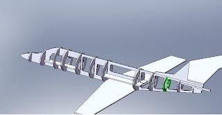
Following the Completion of the big cnc router, I wanted to build a learjet and I'd made the CAD models and plans. Then as it happens, I got bored of messing with solidcam to generate the GCodes and I cut the parts by hand..

this is the Fuselage.

Nose section,Reminds me of a duck...
I'm using the wing in a generic P51 mustang look alike that is awaiting testing. Long thing slender wing, plenty of lift, low drag, should be intense flying, will video the test flight!

Its taking too much space in my bedroom and is not seeing much use, I'm gutting it and building a CNC mill using a 1kw Router. I've packed the skate bearings and angled alu rails and using Drawer slides for simplicity. It is going to be a simple x - y positioning table with the tool mounted on a pillar with only z- axis. The plan is to use this mill parts for a REPRAP .
Or I might just lob a Plastic extruder on as use it as a Repstrap.. who knows..
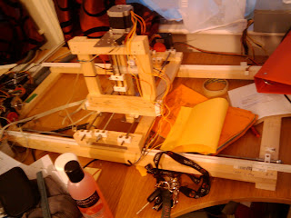
And since I've now built more than 3 machines (5 if you count upgrades) I've gone and skipped making the parts on CAD, making the plans and building the parts from plans... I've gone from sketches...to Solidworks model

and building on the fly, and here is the baby awaiting the installation of the z- axis stepper.


The X and Y axes are calibrated and work, Accuracy again is improved from the previous incarnation.The Drawer slides were a good idea! no wobble, and the turret is very sturdy as well.Gotta love that Rough pine from B&Q. Installed the Lead screw on the Z, geared it as it is a heavy load, I only have to fashion a motor mount for the z stepper and we're in business!
watch this space for the First Milling Test video coming soon!
And oh, Did I mention I have an airframe for the UAV?

CNC milled built up 6mm Depron Wing skinned with 3 mm depron. 1.5 metres span chunky clark y airfoil. Loads of lift, For a wing that weight next to nothing.. overpowered with a big bad brushless typhoon motor and a 10x6 high mounted pusher prop.

the Nacelle was also cnc cut on the router from a Solidworks model. Hurray for home manufacturing!!
Saturday, 23 January 2010
depron learjet! first cnc cut project


F22 raptor semi scale pusher
clark y airfoil - 6 mm depron frame, 3 mm depron skin, flapperons, full moving tail
AUW with a 1050 mah 3 cell lipo 360g . cockpit still needs to be built.awaiting test flight
Learjet, working on G-codes at the mo.
more to come soon!
Thursday, 21 January 2010
CNC project update

I left the last log of this project with Promises of mark 3 in action. Mark 3 work, brilliantly but the ridiculously small working area was an issue.I wanted to make Rc plane kits from large depron sheets. So as soon as i got mk III running , tried a few test cuts and dismantled it! I wanted to rebuild the big one ( mk II ) with the speed of mk III.
Here is a pic of MKIII before I added the Z axis assembly.
I redesigned the mk II Gantry and optimised it for speed.Gone are the heavy mdf panels, a;replaced by light pine beams and open structures, i've also replaced the top and undercarriage with 4 tensioning m6 rods instead. I've learnt that designing ev
erything from the start and then relying on the parts to fit as planned never goes to plan, so all the carriag
es are adjustable using the thread rods. The Gantry is now super light, adjusted for minimum friction at minimum wobble.

I have geared up the stepper motors by 5, the transmission is via a timing belt and
abs timing pulleys.I have also changed the cutting bit for a 6mm 2 flute dremel router bit.perfect for depron. I still have to make a video, but the cutting speed of mkIV is amazing, accuracy is pretty decent, cutting circles is pretty accurate.
I am now at the stage
of designing kits for cutting

MKIV ready to accept her next assignment. Next step: A dust collection system and plastic extruding head! turn mark IV into a repstrap!
Wednesday, 16 December 2009


Saturday, 12 December 2009
Xbox first person shooter gun!
A short lived project of mine, that i decided to do for a laugh!
Basically, the idea was to replace the potentiometers in an xbox joystick with digital potentiometers controlled by an arduino. the voltage output through the digi-pots are directly correlated to positional data extracted from a wii motion plus a Wii nunchuk. The data is extracted from both sensors, kalman filtered and output thru the digipot.
the whole gizmo is fixed on a gunshaped frame ( I used to play call of duy 4 modern warfare- so its base on a heckler-Koch G36 for us geeks out there!
I added a potentiometer to tweak the sensitivity of the device. IN the videos below you can see the device in action while playing Halo 2 on my old xbox. There was no way i was sacrificing one of my 360 controllers for this! The drawback with this prject was that the sensors could not provide me with a yaw axis, so to look left and right, i had to tilt the gun left and right, instead of sweeping around like i woould in reality!The hardware limitation meant that to be able to do that , i would need to invest in a magnetometer. In the current economic climate, that was a bit unlikely!
Anyway, here are the test videos! enjoy!
references used in this project!
http://randomhacksofboredom.blogspot.com/2009/06/wii-motion-plus-arduino-love.html
thanks!
CNC router projects
YO, I had been contemplating with the idea of owning a CNC machine for some year now. (proably since chilhood when i learnt the word CNC). Buying one is out of the question, too expensive and again, against the Ghetto engineering Ethos. Which leaves the only option to make one!
I started out with a budget of a £ 100 and intended to use an arduino as the brain for the machine.I started the build and £ 100 pounds later i ended up with something that looked like this:
 The frame was built out of pine wood strips , screws and plastic cuboid thingies held it together.I used plastic, aluminium extrusions and plates, steel rods for railings and an M6 all thread rod as lead screw.
I purchased 2 stepper motors off the makerbot website , that i had just discovered! i intended to use an RC servo for the z axis, ghetto engineering frugality...
I later regreted that decision and bought another stepper when I realised that mixing servos and steppers would complicate the controlling electronic. SO that was changed! I bought some stepper controller ICs from farnell and set to design a CNC controller from scratch, which i did get to work on a breadboard stage, but i realised that i had set myself a herculean task that involved reinventing the wheel when i came to writing the source code to change g-code into actual stepper control signals, and my good senses kicked in and i started looking for a decently priced stepper controller! i found a decent 4 axis stepper controller manufactured and sold by a chap in Hungary , that was as godsend, it worked brilliantly!
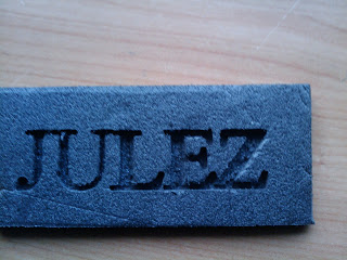
So as i tested The machine with a biro as a tool and figured out how to rig a z axis meanwhile and make a cheap cutting tool..
here is the first job ever done on the machine ( there was no z axis hence the line bet ween each letter).
Considering I had not designed this, I had merely built it on the fly, I was chuffed by the results! I built and tested a couple of rotating tools to to mount on the machine ( to cut depron foam to make rc planes and uavs)
after installing a the cutter bit!
 Below are a couple of clips of the cnc machine being tested!
After a few succesful test cuts, i decided to design a monster machine with a bed of 1000mm x 1000m , big enough to place a whole sheet of 6mm depron and cut aircraft kits. I also wanted an indexing turntable to be able to explore the third dimension and cut 3d objects...
So i set of to Portugal on Holiday and spent my evenings sipping moscatel de setubal and sketching my next project. When I got back to Leeds, I sat at my pc for about a Week with my best friend Solidworks and got cracking transposing my sketches into a 3d ASSEMBLY, printed the engineering drawings for my components. I burst into a an evil Laugh full of glee when when I compiled my Bill of Materials and the cost came up to £200 pounds, this included a nice electric circular saw essencial for the precise MDF cuts required for the jobs, with G clamps bought at the pound shop - a pound for 3 G clamps. ( still using them to this day) ; Ghetto engineering indeed. I recycled the steppers and controller from the Mark 1 cnc router and got building for a fortnight.
From concept to reality...
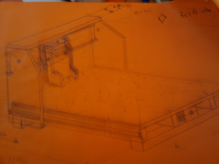
Left, sketches made on holiday while sipping Moscatel de setubal
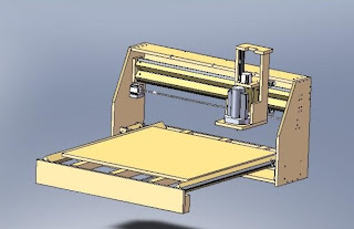
Back from holiday, the solidworks assembly drawn, plans for the parts draughted and printed, BOM sorted and cost finalised. OFf to screw fix and B&Q we went.... Transporting the timber in my Toyota Ago was a fun experience...Gotta love the cutting service B&Q offer, I had designed the parts in a way that i only had minimal cutting to do after the chap at the timber yard sliced my mdf sheet!
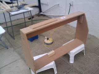 Gantry assembled! I later redesigned it and rebuilt it a bit taller for extra z- axis movement!
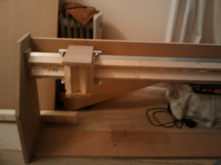 Y -axis carriage added, the movement is soooo smooth! hardly any friction. Bearings Recycled from hardly used Roller blades from my teenage years. Recurring theme, Ghetto Engineering baby!
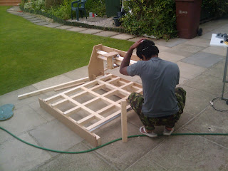
Installing the gantry on the base! Scary moments! its make or break! will the alignment be true?will the axes be perpendicular??
OF course no, the axes were at 87 degress. over small Jobs, insignificant but when cutting large jobs, makes all the difference! the gantry was later rebuilt taller as mentioned above and the y axis carriage rail could pivot for adjustment after final assembly! Lesson learnt!
Testing the motion, for such a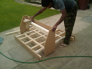 heavy gantry, i was pleasantly surprised that no much force was required to move it! using an M6 all thread rod as a leadscrew(purpose built lead screw are soooo exorbitantly priced) should provide a lot of force!!
 Voila! Now i just need to Shoulder Press this beast to my Lab/office/bedroom and install the motors, lead screw, end stop optical switches, the cutting tool and finally the work surface!
SO much Fun to be had!
ouple of weeks later! motors and everything installed.Before trying a test cut with a cutting tool, I used a felt tipped pen to test out the machine after calibrating the scaling and adjusting the axes for true perpendicularness or is it perpendicularity?does it work? course it does!! Remember your 6 P's
Proper
Planning and
Preparation
Prevents
Poor
Performance
Here is the first time I tested the machine:
Note, I decided to get the machine to write SEXY , not because I think the machine is hot,Nor because I am vain, but becuase the word is short and provides a a combination of curves and angled lines perfect for testing a CNC machine, a bit like the " hello world" used in electronics when testing...
Anyway, lets mount the cutting tool and see how it goes!
Time for the first test cut using a rotary tool ( of my own design, my dremel is used too often to be sacrificed for this project!, i used a speed 480 motor from an old aircraft, we all fly brushless these days.., used a motor shaft adaptor to hold the dremel end mill bit, and joined that to the motor using a shaft linkage from a RC boat,Used an little turned aluminium thingy from a sliding door as a flywheel to gyro stabilise the business and reduce vibrations.The bearing was salvaged from a burnt out brushless motor.I know dont ask, Ghetto engineering.Everything is recycled.
Hmm, it works, lets try it for the purpose it was designed for! cutting aircraft kits! lets see the first kit cut!
Verdict: accurate beyond my wildest dreams, but A bit slow. Must gear the leadscrews to increase the working speed. Sadly I never got to modify the machine for more speed. I Am currently out of a job and job hunting. Shelling £50 quids to buy aluminium pulleys and toothed belts is a out of the question, so between applying for jobs, i decided to recycle the parts and build a smaller mark III machine. Faster but with a smaller footprint,using cheap plastic gears from hobbicraft. 65 pence per gear, bargain.
Mark 3, was built on the fly, having learnt from my mistakes and previous designs , i was able to whip up this version within 3 days recycling components from mark I and II. I still have to complete this baby, but it promises to be as accurate as mark II. Motor tests, (not fimed yet) promise super fast cutting speeds!
Watch this space!
Fropessional Engineer Nick!
I started out with a budget of a £ 100 and intended to use an arduino as the brain for the machine.I started the build and £ 100 pounds later i ended up with something that looked like this:
 The frame was built out of pine wood strips , screws and plastic cuboid thingies held it together.I used plastic, aluminium extrusions and plates, steel rods for railings and an M6 all thread rod as lead screw.
I purchased 2 stepper motors off the makerbot website , that i had just discovered! i intended to use an RC servo for the z axis, ghetto engineering frugality...
I later regreted that decision and bought another stepper when I realised that mixing servos and steppers would complicate the controlling electronic. SO that was changed! I bought some stepper controller ICs from farnell and set to design a CNC controller from scratch, which i did get to work on a breadboard stage, but i realised that i had set myself a herculean task that involved reinventing the wheel when i came to writing the source code to change g-code into actual stepper control signals, and my good senses kicked in and i started looking for a decently priced stepper controller! i found a decent 4 axis stepper controller manufactured and sold by a chap in Hungary , that was as godsend, it worked brilliantly!
So as i tested The machine with a biro as a tool and figured out how to rig a z axis meanwhile and make a cheap cutting tool..
here is the first job ever done on the machine ( there was no z axis hence the line bet
 ween each letter).
Considering I had not designed this, I had merely built it on the fly, I was chuffed by the results! I built and tested a couple of rotating tools to to mount on the machine ( to cut depron foam to make rc planes and uavs)
after installing a the cutter bit!
 Below are a couple of clips of the cnc machine being tested!
After a few succesful test cuts, i decided to design a monster machine with a bed of 1000mm x 1000m , big enough to place a whole sheet of 6mm depron and cut aircraft kits. I also wanted an indexing turntable to be able to explore the third dimension and cut 3d objects...
So i set of to Portugal on Holiday and spent my evenings sipping moscatel de setubal and sketching my next project. When I got back to Leeds, I sat at my pc for about a Week with my best friend Solidworks and got cracking transposing my sketches into a 3d ASSEMBLY, printed the engineering drawings for my components. I burst into a an evil Laugh full of glee when when I compiled my Bill of Materials and the cost came up to £200 pounds, this included a nice electric circular saw essencial for the precise MDF cuts required for the jobs, with G clamps bought at the pound shop - a pound for 3 G clamps. ( still using them to this day) ; Ghetto engineering indeed. I recycled the steppers and controller from the Mark 1 cnc router and got building for a fortnight.
From concept to reality...

Left, sketches made on holiday while sipping Moscatel de setubal

Back from holiday, the solidworks assembly drawn, plans for the parts draughted and printed, BOM sorted and cost finalised. OFf to screw fix and B&Q we went.... Transporting the timber in my Toyota Ago was a fun experience...Gotta love the cutting service B&Q offer, I had designed the parts in a way that i only had minimal cutting to do after the chap at the timber yard sliced my mdf sheet!
 Gantry assembled! I later redesigned it and rebuilt it a bit taller for extra z- axis movement!
 Y -axis carriage added, the movement is soooo smooth! hardly any friction. Bearings Recycled from hardly used Roller blades from my teenage years. Recurring theme, Ghetto Engineering baby!
Installing the gantry on the base! Scary moments! its make or break! will the alignment be true?will the axes be perpendicular??
OF course no, the axes were at 87 degress. over small Jobs, insignificant but when cutting large jobs, makes all the difference! the gantry was later rebuilt taller as mentioned above and the y axis carriage rail could pivot for adjustment after final assembly! Lesson learnt!
Testing the motion, for such a
 heavy gantry, i was pleasantly surprised that no much force was required to move it! using an M6 all thread rod as a leadscrew(purpose built lead screw are soooo exorbitantly priced) should provide a lot of force!!
 Voila! Now i just need to Shoulder Press this beast to my Lab/office/bedroom and install the motors, lead screw, end stop optical switches, the cutting tool and finally the work surface!
SO much Fun to be had!
ouple of weeks later! motors and everything installed.Before trying a test cut with a cutting tool, I used a felt tipped pen to test out the machine after calibrating the scaling and adjusting the axes for true perpendicularness or is it perpendicularity?does it work? course it does!! Remember your 6 P's
Proper
Planning and
Preparation
Prevents
Poor
Performance
Here is the first time I tested the machine:
Note, I decided to get the machine to write SEXY , not because I think the machine is hot,Nor because I am vain, but becuase the word is short and provides a a combination of curves and angled lines perfect for testing a CNC machine, a bit like the " hello world" used in electronics when testing...
Anyway, lets mount the cutting tool and see how it goes!
Time for the first test cut using a rotary tool ( of my own design, my dremel is used too often to be sacrificed for this project!, i used a speed 480 motor from an old aircraft, we all fly brushless these days.., used a motor shaft adaptor to hold the dremel end mill bit, and joined that to the motor using a shaft linkage from a RC boat,Used an little turned aluminium thingy from a sliding door as a flywheel to gyro stabilise the business and reduce vibrations.The bearing was salvaged from a burnt out brushless motor.I know dont ask, Ghetto engineering.Everything is recycled.
Hmm, it works, lets try it for the purpose it was designed for! cutting aircraft kits! lets see the first kit cut!
Verdict: accurate beyond my wildest dreams, but A bit slow. Must gear the leadscrews to increase the working speed. Sadly I never got to modify the machine for more speed. I Am currently out of a job and job hunting. Shelling £50 quids to buy aluminium pulleys and toothed belts is a out of the question, so between applying for jobs, i decided to recycle the parts and build a smaller mark III machine. Faster but with a smaller footprint,using cheap plastic gears from hobbicraft. 65 pence per gear, bargain.
Mark 3, was built on the fly, having learnt from my mistakes and previous designs , i was able to whip up this version within 3 days recycling components from mark I and II. I still have to complete this baby, but it promises to be as accurate as mark II. Motor tests, (not fimed yet) promise super fast cutting speeds!
Watch this space!
Fropessional Engineer Nick!
Subscribe to:
Posts (Atom)
